An Overview of Correct Vibratory Bowl Set-Up
By : Bill Nebiolo ,

By : Bill Nebiolo ,
As delivered from the manufacturer, vibratory bowls are set-up to operate in a functional motion pattern. However, future maintenance to replace a faulty motor or if a bowl is relined, or to replace worn-out bearings, may result in a machine with poor mechanical motion once reassembly is complete. Here are some helpful hints to correct this situation.
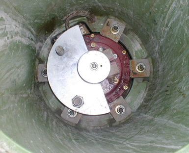
Image 1: Direct drive; driveshaft through motor.
Proper driveshaft rotation is essential when using a vibe bowl and is task one when calibrating a machine. You will find a directional arrow decal affixed; typically, to the machine’s lower access hatch cover. The arrow indicates the correct driveshaft rotation direction. Confirm this is so by opening the bottom access hatch and jogging the motor. The direction of the arrow and driveshaft rotation should match. If the arrow is missing, a direct drive machine; a.k.a. a cartridge machine with a center-mounted, through-motor driveshaft; see image 1, typically rotates counterclockwise.
The driveshaft on an indirect drive machine; one with an external, V-belt driven motor, typically rotates clockwise; see image 2. If rotation is wrong, then the motor is wired into the power panel in reverse. To correct this situation, switch the position of the motor’s hot and neutral wires in the power panel. This will reverse motor polarity and return the driveshaft to the correct rotation direction.
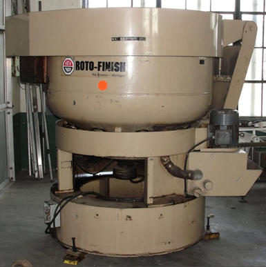
Image 2: Indirect V-belt drive machine
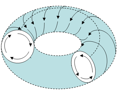
Image 3: Correct helical roll pattern of media
Media has two planes of motion in the vibratory bowl. The first plane of motion is horizontal slide. The second is vertical roll. When combined, the two motions generates a helical coil, see image 3. Once driveshaft rotation is confirmed as correct, observation of the media mass should show, and this is important that its horizontal motion must be opposite to driveshaft rotation. Matching directions means the motor is running backward. Reverse leads to switch polarity as noted above.
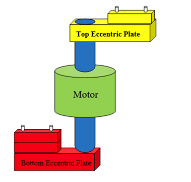
Image 4: Driveshaft and eccentric plates.
Image 4: Driveshaft and eccentric plates.
The driveshaft is equipped with both a top and bottom eccentric plate. Adding or removing weight segments to these plates alters the spiral pattern as well as the mass rolling speed; see image 4. Adding weight segments to the bottom increases bowl amplitude and mass rolling speed. The bowl becomes more aggressive and the parts roll more times per lap around the channel; see image 6. Removing weight from the bottom has the opposite effect: it decreases bowl amplitude and slows mass rolling speed.
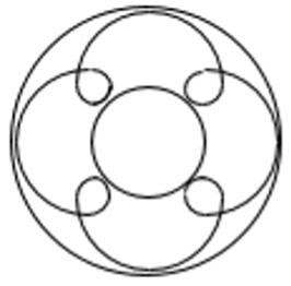
Image 5: Open Spiral Mass Rolling Pattern
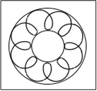
Image 6: Closed Spiral Mass Rolling Pattern
Mass now makes fewer rolls per lap around the channel; see image 5. Adding weight segments to the top opens up the mass spiral rolling pattern. Mass now makes fewer rolls per lap around the channel; see image 5. Removing weight segments yields a tighter mass spiral rolling pattern and mass rolls more times per lap; see image 6.
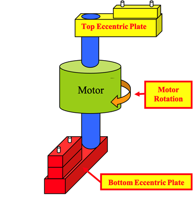
Image 7: 90-degree Lead Angle, Bottom Weight Leading
If you stand above the driveshaft and look directly down onto the top of the driveshaft, it is possible to see that the angle of alignment between the top and bottom weights can be adjusted. See image 7. This shows from the side that the top weight is at 3 o’clock and the bottom weight is at 6 o’clock. This is the typical operating alignment angle of a vibratory bowl; weights at a 90-degree angle. Note the driveshaft on this direct drive motor is rotating clockwise. When observed from overhead — and this is critical — the bottom weight must always lead the top weight into the direction of rotation. This is the weight lead angle. Always set this angle to 90 degrees when setting up a bowl. On all vibe bowls, the lead angle is adjustable and doing so will affect the rolling angle and spiral pattern.
On occasion, an operator may desire to increase or decrease this angle to accommodate the processing of parts having different morphological shapes or metallurgical hardness. Making the lead angle more acute; <90º, speed-up mass rolling speed as it concentrates all weight segments to one side of the driveshaft. The more acute the angle, the more imbalanced the driveshaft becomes and the more eccentrically it spins, thereby increasing rolling speed.
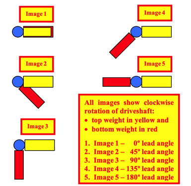
Image 8; Overhead view weight alignment angles
Making the angle more obtuse; >90 degrees, slows down the mass rolling speed as opening the lead angle diffuses the eccentric weights to opposite sides of the driveshaft. The further the weight angle is opened, the more balanced the driveshaft will become tending to temper its eccentric rotation and slow mass rolling speed; see image 8. When adjusting lead angles, the angle is almost always left at 90 degrees. It is almost never made more acute than 80 degrees. Likewise, an obtuse angle of 100 degrees is almost never exceeded. Angles <75 degrees invariably generate rolling speed that is too aggressive. Lead angles >100 degrees will severely open up the mass rolling pattern. At an angle of 130 or 140 degrees, parts placed into the mass will rarely undergo vertical roll and perhaps will horizontally make several laps before rolling just once. This is helpful when processing long skinny parts that may otherwise jackstraw together against one another.
As a quick review, here are the basics of vibe bowl set-up. These rules should be followed for first-time bowl use, start-up of a bowl after maintenance work or if a well-intentioned operator incorrectly adjusts the bowl’s weight settings in a failed attempt at being helpful:
Bitte füllen Sie das folgende Formular aus, um die gewünschte Ressource zu erhalten